Anna Courtney, BSc1, Michael S. Orendurff, PhD2 and Arjan Buis, PhD1
From 1Biomedical Engineering, University of Strathclyde, Glasgow, UK and 2Orthocare Innovations, Seattle, Washington, USA
OBJECTIVE: A recurring complication in trans-tibial prosthetic limb users is “poor socket fit” with painful residuum-socket interfaces, a consequence of excess pressure. This is due to both poor socket fit and poor socket alignment; however, the interaction of these factors has not been quantified. Through evaluation of kinetic data this study aimed to articulate an interaction uniting socket design, alignment and interface pressures. The results will help to refine future studies and will help determine whether sockets can be designed, fitted and aligned to maximize mobility whilst minimizing injurious forces.
METHODS: Interface pressures were recorded throughout ambulation in one user with “optimal (reference) alignment” followed by 5 malalignments in a patellar tendon-bearing and a hydrocast socket.
RESULTS: Marked differences in pressure distribution were discovered when equating the patellar tendon-bearing against the hydrocast socket and when comparing interface pressures from reference with offset alignment. Patellar tendon-bearing sockets were found to be more sensitive to alignment perturbations than hydrocast sockets. A complex interaction was found, with the most prominent finding demonstrating the requisite for attainment of optimal alignment: a translational alignment error of 10 mm can increase maximum peak pressures by 227% (mean 17.5%).
CONCLUSION: Refinements for future trials are described and the necessity for future research into socket design, alignment and interface pressures has been estabilished.
Key words: alignment; distribution; measurement; perturbations; pressure; prostheses; trans-tibial.
J Rehabil Med 2016; 48: 00–00
Correspondence address: Arjan Buis, Biomedical Engineering, University of Strathclyde, Wolfson Centre, 106 Rottenrow, Glasgow, G4 0NW, UK. E-mail: arjan.buis@strath.ac.uk
Accepted Jan 29, 2016; Epub ahead of print Mar 14, 2016
INTRODUCTION
The number of primary prosthetic referrals to UK centres is increasing, with approximately 70% of these being trans-tibial level (1). Amputees who ambulate with prostheses can encounter numerous complications that impede their ability to remain successful users. A recurring complication is “poor socket fit”, with pain at the residuum-socket interface, resulting from areas of high pressure (2). Problematical areas of high pressure are not simply due to poor socket fit but to a combination of poor socket fit and poor socket alignment. Therefore, both factors must be optimal in order to deem a socket a “good fit” (3). Despite Radcliffe’s citation that socket interface pressures (IPs) are a result of various factors (some of the most significant being socket fit, alignment and residuum position with regards to the ground reaction force (GRF)) (4), their interaction has not yet been quantified. Therefore, there is currently no consensus on how to achieve and quantitatively confirm a “good socket fit”.
Alignment is defined as the spatial relationship between the socket and the other components of a prosthesis and is a 2-step procedure consisting of static, superseded by dynamic alignment (5). Possible consequences of high pressure can be: ambulatory discomfort, skin lesions, gait deviations, increased energy expenditure, a reduction in activity and, ultimately, non-compliance (2, 5–6). Therefore, due to prevalent reductions in activity, lower-limb amputees have an increased predisposition towards developing co-morbidities such as obesity and cardiovascular disease (3). It is consequently of utmost importance, as voiced by users’ themselves (7), to achieve better fitting sockets with increased comfort and performance, to minimize development of the above risks.
This pilot study aimed to augment our current knowledge by documenting the effect and articulating an interaction between socket design, alignment and IPs in one user using 2 conceptually dissimilar socket designs over 5 alignment perturbations. The eventual aim is to utilize this study’s findings to refine full-scale clinical trials to determine whether sockets can be designed, fitted and aligned to maximize users’ mobility while minimizing IPs.
METHODS
Ethics
Strathclyde University Ethics Committee granted ethical approval prior to participant contact.
Participant
The participant was an active user with no residuum problems (Table I).
|
Table I. Subject and prosthesis information |
|
|
Parameter |
Subject 1 |
|
Sex |
Male |
|
Date of birth |
2 June 1946 |
|
Body weight, kg |
69.9 |
|
Height, m |
1.65 |
|
Date of amputation |
Partial foot in 1992, Revised to trans-tibial in 1995 |
|
Cause of amputation |
Trauma: crush injury |
|
Side of amputation |
Left |
|
Years of prosthetic use |
1995 onwards |
|
Current prescription |
Total surface bearing (TSB) socket, suction suspension: polyurethane liner, silicone sleeve, one-way expulsion valve, multi-axial with dynamic response foot |
|
Residuum length (mid-patella-tendon to distal tibia), cm |
12.5 |
|
Residuum length (mid-patella-tendon to end of soft tissues), cm |
14 |
|
Prosthetic limb length (mid-patella-tendon to bottom of foot), cm |
41 |
|
Qualitative description of residuum |
Cylindrical in shape, prominent cut end of tibia (especially anteriorly, but not problematic) |
|
Clinical comments |
Slight laxity of collateral ligaments |
Instrumentation
Prosthesis. Figs 1 and 2 and Table II highlight key information regarding used prostheses. Bench and dynamic alignment were performed until the participant was comfortable and the prosthetist satisfied. The prosthesis was then deemed optimally aligned. This “optimal alignment” is denoted below as “reference alignment”.
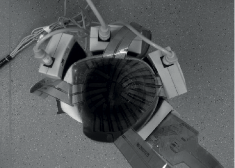
Fig. 1. Tekscan™ sensor placement.
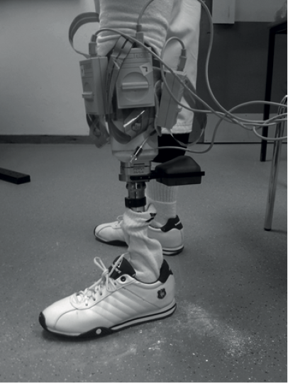
Fig. 2. Prosthesis donned with Tekscan™ system in situ.
|
Table II. Information regarding prosthesis used in study |
||
|
|
PTB |
Hydrocast |
|
Casted and fitted by |
Chief investigator, a certified prosthetist |
Chief investigator, a certified prosthetist |
|
Material |
Thermoplastic |
Thermoplastic |
|
Foot |
SACH |
SACH |
|
Suspension |
Supracondylar |
Pin and lock |
|
PTB: patellar tendon-bearing; SACH: solid-ankle, cushion-heel. |
||
Pressure measurement device. The Tekscan™ (Tekscan, Inc., Boston, USA) system entails pressure sensors, scanning electronics and software that record dynamic pressures at the residuum-socket interface. Four Tekscan™ transducer arrangements were incorporated into both sockets without overlap (anterior, lateral, medial, and posterior), each consisting of 96 individual sensors (producing a total sensing area of 62,000 mm2) (Figs 1 and 2). Known issues of sensor drift and calibration error were corrected by using a unique in situ air bladder calibration system within the socket, as described previously (2).
Alignment offset device. Alignment offset was documented using the Compas™ System (comprising a Smart Pyramid™, a Compas™ Master Unit and software) (Orthocare Innovations, Mountlake Terrace, WA, USA). The Smart Pyramid™ was mounted distal to the socket and incorporated electric moment measuring sensors. The Master Unit attached into the Smart Pyramid™ when data acquisition was required. The Master Unit connected to a host computer, the user ambulated and data was collected concomitantly.
Protocol/procedure resulting in data collection
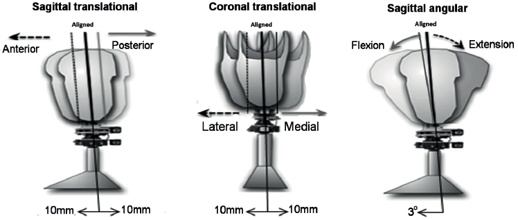
The Tekscan™ and Compas™ systems were fitted to the prostheses and alignment was performed in order to reach the reference alignment as determined by researchers and participant. The participant ambulated at a self-selected cadence and data was collected. Reference alignment was set as baseline on Compas™ and the process was repeated with each prosthesis across translational perturbations of 10 mm anteriorly, laterally, medially and posteriorly and an angular perturbation of 3° flexion (Fig. 3). Perturbations were selected in a randomized order and the participant was blinded to chosen perturbations. Data used for analysis arose from central steps to decrease inaccuracies.
Data analysis
Tekscan™ software was utilized to gather data from the sensors. Graphs and tables were then produced in Microsoft Excel to analyse these data.
Produced data represented mean pressures acting over 96 individual sensors. Consequently, peak pressures within the sensors were masked. Maximum pressures were chosen as the variable of interest since they have the greatest potential to impair tissue viability. Through use of Tekscan™ software these localities of peak pressure within each sensor were highlighted.
RESULTS
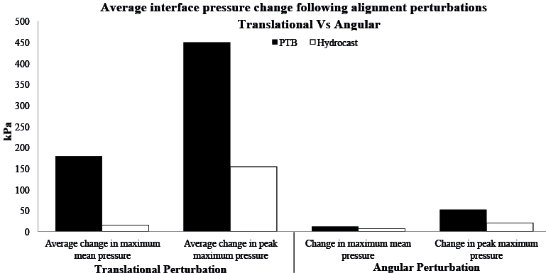
Fig. 4 demonstrates the variant of the mean pressure acting on the medial sensors throughout a stance phase in both socket designs following the specific alignment perturbation. The majority of graphs produced for all 4 sensors follow a dual-peaked wave-form pattern (shown in Fig. 4 for the medial sensors). Fig. 5 highlights the numerical change (delta, ∆) in IP for each alignment perturbation in each socket design. Fig. 6 represents mean IP changes following translational and then angular alignment perturbations (compared with “reference alignment”). Using biomechanical principles, Table III explores the theoretical socket reaction moments and localities of maximum peak pressures following each perturbation, then the anatomical location of peak pressures on the residuum. Graphical representations of these localities are shown in Fig. 7A. Fig. 7B represents the threshold used to demonstrate pressure gradient.
DISCUSSION
This case study examined the change in socket IPs during alignment perturbations in 2 types of transtibial sockets. A general bimodal pressure pattern was observed across the gait cycle, similar to that found in previous research (2). This pattern is similar to the vertical GRF pattern, suggesting that most pressure transmitted to the residuum is associated with axial loading in stance. Pronounced differences in pressure magnitude and distribution were discovered when comparing the patellar tendon-bearing (PTB) against the hydrocast socket in the measurement of IPs from reference alignment with offset alignment.
The explored sockets utilize differing design philosophies for pressure transmission. The PTB socket applies specific loads to pressure-tolerant areas, whereas the hydrocast socket aims to dispense pressure uniformly through the “stiffest path principle” (8). It is advocated that hydrocast sockets have a greater ability to generate “ideal” pressure distribution together with a reduction in internal shear (2, 8).
The most prominent and anticipated finding was that altering alignment altered socket IPs (Fig. 4). Whilst it would have been desirable to carry out hypothesis testing and statistical analysis, this was not possible with a single participant.
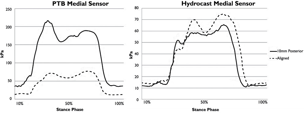
Fig. 4. Residual limb-socket mean interface pressures at reference alignment and at an offset of 10 mm posterior in (A) patellar tendon-bearing (PTB) socket and (B) hydrocast socket.
When analysing pressure magnitude differences with alignment perturbations, it was evident that the socket designs experienced dissimilar alterations. This was explored through numerical and graphical analysis of the difference (Fig. 5). Based on our measurements this might indicate that socket design alters IP distribution.
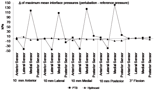
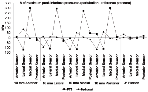
Fig. 5. Change (∆ = perturbation pressure – reference pressure) in (A) maximum mean and (B) peak interface pressures (IPs) with alignment perturbations.
Figs 5 and 6 highlight an increased range of IP change for PTB over hydrocast sockets. This is clinically relevant as it proposes that PTB sockets appear more sensitive to alignment perturbations than hydrocast sockets; suggesting that attainment of optimal alignment in PTB sockets is absolutely crucial to ensure optimal pressure distribution, whereas hydrocast sockets may hold greater flexibility for error.
When alignment is altered the line of action of the GRF also changes, which can modify socket reaction moments (anterior-posterior (AP) and/or medial-lateral (ML)). This positional change of the GRF should theoretically be identical regardless of socket design. As identical alignment perturbations did not cause identical alterations in IPs when comparing both socket designs, it can be established that IPs are not solely dependent on 1 individual factor (GRF), but instead upon a combination of numerous factors. However, to confirm this, the relationship of the GRF and the socket would need to be recorded. Due to the limitations of this study, this was not possible. Nevertheless, it is possible to analyse localities of maximum peak pressures (hence internal residual bony movement) and determine if they lie in accordance with expected socket reaction moments following the performed alignment perturbation. Tables III and IV demonstrate that not all pressure profiles comply with the theoretical principles Radcliffe cited on sole calculation of the position of the GRF with regards to the socket (4).
|
Table III. Expected socket reaction moments and maximum peak pressures following each alignment perturbation vs found localities |
|||||
|
Perturbation |
Theoretical external socket reaction moment |
Theoretical areas of increased pressure |
Socket design |
Discovered area of peak pressure from results |
Does the theory agree with the finding? |
|
Reference |
Adduction moment |
Medially-proximally and laterally-distally |
PTB |
Popliteal fossa |
No |
|
|
Hydrocast |
Anteriorly-distally; “kick-point” |
No |
||
|
10 mm anterior |
Increased knee flexion moment |
Anteriorly-distally and posteriorly-proximally |
PTB |
Medially |
No |
|
|
Hydrocast |
Anteriorly-distally; “kick-point” |
Yes |
||
|
10 mm lateral |
Increased adduction moment |
Laterally-distally and medially-proximally |
PTB |
Medially from mid to proximal knee level |
Yes |
|
|
|
Hydrocast |
Anteriorly-distally; “kick-point” |
No |
|
|
10 mm medial |
Increased abduction moment |
Laterally-proximally and medially-distally |
PTB |
Medially at the mid-knee region |
Yes – Relative |
|
|
|
Hydrocast |
Laterally-proximally (region of fibular head) |
Yes |
|
|
10 mm posterior |
Increased knee extension moment |
Posteriorly-distally and anteriorly-proximally. |
PTB |
Medially at the mid-knee level |
No |
|
|
|
Hydrocast |
Laterally-proximally (region of fibular head) |
No |
|
|
3° Flexion |
Increased knee flexion moment |
Anteriorly-distally and posterior-proximally |
PTB |
Popliteal fossa |
Yes |
|
|
Hydrocast |
Anteriorly-distally; “kick-point” |
Yes |
||
While still assessing Table III and Fig. 7A it is also evident that regions of high pressure appear over bony prominences in the hydrocast socket, whereas in the PTB socket they appear over intentionally loaded areas. One must also consider the presence of a distal umbrella in the hydrocast socket. These umbrellas may theoretically increase pressure distally, which may be a factor in explaining why peak pressures are often highlighted distal-anteriorly in the hydrocast socket. One would need a larger sample size to determine whether this is characteristic of the “kick-point” of the tibia, or due to the umbrella. If it is due to the “kick-point”, this would be in accordance with the theoretical principles of each design. Results show that regardless of alignment, maximum mean and peak pressures were most commonly recorded in the PTB socket.
Fig. 5 also shows that alignment perturbations had greatest, and localized, effect on ML IPs. Medial IPs generally increased with all perturbations while lateral pressures generally decreased. These findings introduce the supposition that sagittal plane perturbations alter coronal plane pressures (ML) to a larger degree than sagittal pressures (AP); which was not the foreseen prognosis. This is clinically relevant as it proves that alignment should be assessed in all planes before attempting to correct an error in 1 (with current clinical practice, this should be done through use of a laser at bench alignment).
Through utilization of the threshold scale (Fig. 7B), the diagrams in Fig. 7A. show recorded pressure gradients. Steep pressure gradients produce greater levels of shear stress (2). Shear stress poses the greatest risk of tissue damage (9) and should therefore be minimized in order to maximize socket efficiency. Fig. 7A illustrates that the PTB socket appears to have a larger surface area experiencing high pressure; however, hydrocast pressures appear to have steeper gradients. This suggests that hydrocast sockets experience increased shear, which is contrary to primary objectives of hydrocast socket design (8). In order to draw final conclusions from this study, pressure gradients from all 4 transducer arrangements would need to be fully analysed, or shear recorded.
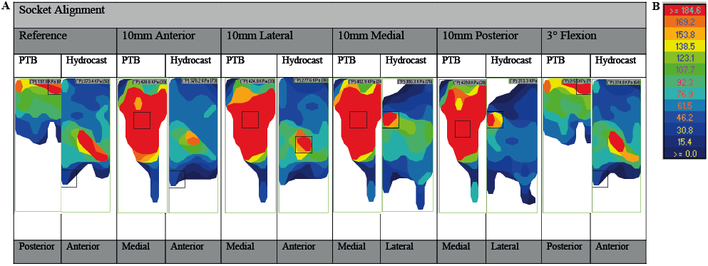
Fig. 7. (A) Graphical localities of peak sensor pressures in both socket designs following alignment perturbations. Images run proximal to distal and left to right. (B) Threshold used to demonstrate recorded pressure gradient (kPa). PTB: patellar tendon-bearing.
This pilot study therefore found no constant factor of change in IPs for the reference alignment against the malaligned sockets when comparing the socket designs for this individual. The results of another study may support this idea that data may be “uniquely systematic” for each individual (10). This paper suggested that the non-adaptive person may have a linear relationship with alignment, whereas the adaptive person may have a sigmoid alignment-pressure relationship. Consequently, the individual results of this study have shown the importance of attaining a biomechanically correct alignment by highlighting that translational perturbations of merely 10 mm can increase mean and peak pressures by 183% and 227%, respectively (Fig. 5) (mean 11.3 and 17.5%, respectively). A translational perturbation of 10 mm lies within the scope of error demonstrated during numerous alignments by the same prosthetist treating one user (5), suggesting that this magnitude of error is common in clinic. By showing a complex interaction between IPs and alignment, this pilot study has begun to highlight the absolute necessity for development of an objective method to analyse prosthetic fit and evaluation, in order to reduce subjective clinical bias.
This therefore suggests that a repeated measures design is essential; with a large enough n to define the different sub-populations of individuals or socket types that are sensitive to alignment changes, alongside allowing for hypothesis testing.
There is a lack of literature regarding socket design vs alignment IP interaction and thus further studies are required in order to draw definitive conclusions. Recommendations for future research would include utilizing a larger n, assessing a larger number of perturbations, utilizing the Compas™ system to record socket reaction moments throughout stance and proximal/distal division of transducer arrangements. This study measured orthogonal pressure at the residuum-socket interface and utilized pressure gradient analysis to assess shear. Transducers capable of concurrently measuring orthogonal pressure and shear stress would improve accuracy. Utilizing a larger n whilst additionally recording gait speed could improve accuracy of results, as varying cadence can alter the ankle moment and could therefore affect socket reaction moments and ultimately, IPs. In addition, the need to ascertain an accurate maximally clinically recommend “safe” IP needs reassessed.
Although no clear link between socket design, alignment and IPs has been recognized, the idea that people may be unique, or adapt in unique ways, to alignment perturbations in different socket designs has been highlighted. The clinical relevance and vast necessity for additional research in this area has been emphasized.
Data attained from results of future multi-centre clinical trials will allow for statistical analysis. It is hoped by eventually elucidating the relationship between socket design, alignment and IPs it will become apparent what constitutes optimal socket fit. Herein lies true potential to ease attainment of better fitting sockets (i.e. improved fit and alignment), which would be advantageous to the clinician (reducing the time and related costs of producing well-fitting sockets) and the user (achieving comfort and ideally, increasing activity).
REFERENCES
